
A liner may arrive intact without surface damage, but installers may encounter resistance when placing the liner flush against a concrete wall or around a pipe opening. On occasion, it’s due to a poor cut, a ragged edge, or a fabricated part based on measurements never validated. Or, the material is fine but the geometry of the piece does not match up with the installation parameters. They all lead to unnecessary cutting and fitting work for installations in tight spaces around a concrete structure. For manufacturers, it’s the logistics of catching the work that can impact installation, and then verifying those dimensions are correct before finished sections leave the shop.
Why Can Dimensional Errors Cause Problems During CPL Installation?
A panel’s overall dimensions do not tell the whole story. An installer may be able to accommodate a small difference in length along an unrestricted edge but have little room to correct an opening that does not align with a pipe.
Check the position, not just the size
Imagine a rectangular panel with a pipe opening close to one of the corners. The diameter of the opening could be the same as the drawing but its centre could be wrong because the operator measured from the edge which has been cut off.
Openings greater than the specified size may not be an acceptable correction. It may alter the joint form intended and there may be inadequate remaining thickness around the penetration.
The factory must determine the actual reference dimension before deciding if the part can be made correct.
| Observed problem | Possible cause | Factory verification |
|---|---|---|
| Opening does not align | Wrong measurement reference | Check opening center against drawing datum |
| Uneven joint gap | Inaccurate edge cutting | Measure edge straightness |
| Corner section fits poorly | Incorrect angle | Compare with approved geometry |
| Several panels misalign | Accumulated dimensional variation | Check assembly dimensions |
These findings require different responses. Correcting a cutting machine will not resolve an error caused by using the wrong drawing reference.
Assembly accuracy matters
A panel could individually have its size requirement but might not have assembled in the way it was expected to. This comes from the fact that subtle variation can sum when many pieces come together as one connected surface.
With custom items, observing the relationship between adjacent pieces can reveal issues missed by individual measurements.
This is particularly useful around penetrations and other details found in existing concrete structures, where accurate site measurements may not be available until rehabilitation work begins.
What Manufacturing Defects Can Affect the Anchor Structure?
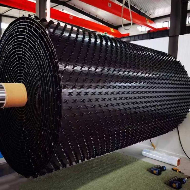
The shape of the rear anchoring profile serves a different role to the exposed protective face. Its role is to mechanically engage concrete and therefore its shape is an important manufacturing feature.
Compared to the working face, the anchoring side is hard to check after installation.
Distinguish extrusion defects from later damage
Improper forming or dimensional irregularities during extrusion if the extrusion process does not ensure the required profile shape. Production evidence is needed and not a visual assumption.
A distorted anchor discovered after cutting presents another possibility: the profile may have been satisfactory when formed but damaged during handling.
Inspection records at different stages help distinguish these situations.
For example, where a section passes forming inspection but later shows local anchor damage, the investigation can examine cutting supports, movement between workstations, and storage conditions.
What should inspectors measure?
The approved drawing determines the relevant checks. Depending on the specified profile, these may include anchor height, shape, continuity, and visible deformation.
The industrial applications of concrete protective liners illustrate different uses of anchored polymer protection systems. The actual acceptance criteria, however, must come from the selected product specification.
An irregularity is a reason for inspection and evaluation. It does not automatically establish how a completed concrete structure would perform.
How Can Poor Edge Preparation Interfere With Field Welding?
In the field, welding is started after the parts are fitted up. When edges cannot be located to agree with the joints approved detail, no welding variables can rectify the shape.
This distinction can prevent the investigation of the wrong problem.
An uneven gap needs a dimensional check
Imagine two sections are joined at a wall-to-floor junction. They align at one end but diverge towards the opposite end.
However, if the difference is true, the installer must determine whether it is attributed to the factory cutting, the panel placement or the concrete.
Another verification is made prior to sending, especially for fabricated corners or areas that must fit together on many edges.
If the variance occurred in machine cutting, the factory can explore marking, how it is supported while machining and equipment set up.
Some details are better finished on site
Envision 2 areas joined at a wall-to-floor junction. They line up at one close however they taper at the other end. If this difference is valid, the installer will then need to decide as to whether the difference is due to factory cut, the panel placement or the concrete. Another check before transmitting, particularly on corners fabricated or areas that are going to fit against many edges. If the variance was found when machine cutting then the factory can investigate marking, where it is supported during machining and fixture set up.
The need to distinguish confirmed geometry from uncertain details also arises in secondary containment structures, where corners, penetrations, and transitions can complicate fabrication.
Material identity should remain traceable whenever the specified welding method requires compatible thermoplastic consumables.
Where Should Factories Inspect Fabricated Liner Components?
A final check can save a nonconforming part being shipped. An earlier inspection can save the defect being created in the first place.
This becomes significant where a custom section has many similar openings or sections of material that are fabricated.
Inspect before irreversible work
The correction for a marking error found prior to cutting is different from the correction for the same error if it were found after cutting.
Confirming key measurements at the marking stage will ensure the wrong opening does not get produced on an ongoing basis.
Similarly, anchor geometry can be checked after forming and again after operations that might damage the profile.
| Production stage | Inspection focus |
|---|---|
| Drawing release | Approved revision and reference dimensions |
| After extrusion | Sheet and anchor geometry |
| Before cutting | Opening positions and markings |
| After fabrication | Edges, dimensions, special details |
| Before shipment | Component identification and condition |
This is an inspection-planning example rather than a universal acceptance standard. Actual tolerances and sampling frequency need to follow the approved quality plan.
Keep the original defect in the record
Imagine a shop constantly reworking openings cut into the wrong reference edge. If every piece of parts made are defect-free, the problem may only be revealed in the final records.
A nonconformance report should list the original deviation, designated component, drawing revision, correction, and reinspection result.
This data allows us to search the marking guidance or reference system, rather than line up each piece of data as an individual error.
What Should Manufacturers Confirm Before Custom Fabrication Starts?
Some fabrication problems are caused by incorrect workshop operations. Others begin because production receives incomplete engineering information.
A manufacturer may accurately follow a drawing that no longer represents the structure being built.
Drawing revisions need a clear release process
If a revision relocates an opening, not all of the parts that are fabrications will probably be impacted. Before the production crew moves forward, they should determine which of the pieces are based on the revision.
For example, in a more complex order, it may involve putting apart parts of an order until other parts are confirmed.
A clear drawing reference on the production record makes that decision easier.
Confirm the division between factory and site work
A manufacturer should be aware of which information is built up entirely in advance and which ones are subjected to site adjustments.
This especially applies to structures where dimensions and positions of piping are possibly not in accordance with the available drawings.
Practical handover will specify confirmed sizes, remaining measurements, referenced components and agreed upon field-fitting allowances.
Identification also matters after production. Two similar-looking corner pieces can belong at different locations. Without clear references, installers may attempt to position the wrong component even when both pieces were fabricated correctly.
Protecting finished edges and anchoring features during handling helps preserve the accepted condition until delivery.
Need Help Coordinating CPL Fabrication Requirements?
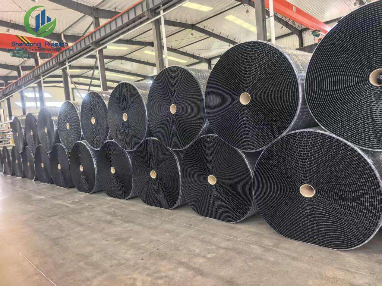
Once project drawings and installation responsibilities are established, fabrication can be reviewed against defined material and dimensional requirements. Shandong Ruinato Environmental Protection Technology Co., Ltd. manufactures engineering plastic materials, including Concrete Protective Liner (CPL). Published specifications include Type A & Type B configurations with heights of 13mm and 19mm anchor heights respectively. Available plate thicknesses are 1.5mm through to 6.0mm. Approved product specifications state 1 time extrusion molding with banner width of 2,000mm and 1,960mm anchor length. This information will be helpful for confirming the fabricated dimensions, anchor requirements, drawing references and inspection plans prior to manufacturing.
Conclusion
Installation issues caused by fabrication usually start from an avoidable, identifiable issue, such as a wrong reference point, a bad cut, a damaged anchor, or something built to old information. Detecting that issue is more important than continually fixing it in the finished article. Fabricators can limit unnecessary site work by verifying essential dimensions prior to cutting, separating forming issues from handling damage, and predicting the fit of unusual parts. For orders, the quality of the drawings is just as important as design verification in the shop, and final authority to make adjustments on site.
FAQs
1. Why can a correctly sized liner still fail to fit?
Overall dimensions may be correct while an opening or reference edge is incorrectly positioned. Installation depends on how adjoining components relate to one another, so individual length and width measurements may not identify every fitting problem.
2. How can factories identify anchor damage introduced after extrusion?
Inspect the profile after forming and again following cutting or other handling operations. Comparing those records can help determine whether a defect arose during extrusion or was introduced later.
3. Should all custom openings be completed at the factory?
Not necessarily. Fully fabricated openings are more practical when the actual dimensions are confirmed. Where site geometry remains uncertain, an approved allowance for final fitting may be appropriate.
4. What causes repeated dimensional errors during cutting?
Potential causes of this include false referencing edges, out of date drawings, incorrect marking, inappropriate fixtures or incorrect set up of cutting equipment. It is worthwhile gathering data of a number of affected components to establish if they have a common origin.
5. What documents should accompany custom fabricated liner sections?
Existing drawings of fabrication, component layout, critical dimensions, material specifications, documented exceptions, and documented field fit instructions can give installers an idea of where parts fit and what needs to be done.